Jig Print - Operations
Start jig printing setting
- Select the [Jig Print] check box on the [Jig Print] screen.
- This allows the various [Jig Print] function settings to be edited.
Edit a jig template
Create a new jig template
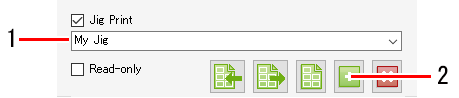
- Enter the name of the new jig template to be set in the jig template selection input box.
- Click the [
 ] icon.
- The [Jig Definition] tab appears.
[Jig] | : | Sets the overall jig size, print origin position, and skew. Set the skew as the angle (-45° to 45°) with respect to the lower right of the jig. |

- Skewing the jig also skews each material on the jig.
Adjust the skew to correct tilt with respect to the table. - Skewing jigs will cause job outlines and direct parts to become slightly jagged.
Jagged edges will become particularly noticeable with low-resolution raster data.
When skewing raster data, data should be created using a resolution close to the print resolution.
[Material] | : | Sets the individual material size, number, first material position, and placement. Size is set as valid print size (minimum 25.4 mm), count is set up to 99 x 99 (total 9,801), and interval is set as pitch (width is the distance from the right-hand edge of the right-hand material, and height is the distance from the bottom edge of the material below). |
[Adjustment] | : | Selects a material and finely adjusts its position. Select using the material pull-down menu or click the material in the preview. The selected material is shown in the preview in a red box. |
Edit a jig template
- Select a jig template from the jig template selection pull-down menu.
- Select the [Jig Definition] tab.
- Click the [] icon after configuring the various jig settings.
- The jig template settings will be overwritten.

- The [Entire print area] jig template cannot be edited.
Delete a jig template
- Select a jig template from the jig template selection pull-down menu.
- Click the [
 ] icon.
- The jig template will be deleted.
- The [Entire print area] jig template cannot be deleted.
Print a jig outline
- Click the [
 ] icon.
- The [Print jig outline] dialog appears.

[Favorite] | : | Selects the favorite used when printing an outline. |
[Line Width] | : | Sets the outline width. |
[Color] | : | Sets the outline color. |
[Offset] | : | Sets the method for drawing the jig rectangle. |
(The red box in the following figure indicates the jig rectangle, and the black lines indicate the outlines printed.) | ||
Offset | mm | Drawing setting
| |
Select
| For 0 | Prints an outline with the jig rectangle in the center of the lines. |
|
Greater than 0 | Prints an outline outside the jig rectangle. |
| |
Half of line width | No setting | Prints an outline touching the jig rectangle on the outside. |
|


- Click [Print].
- The outline is printed.
- Click [Save].
- A PDF file is created.
Enlarge or reduce a jig print job
- Select the [Valid] check box in [Scale] on the [Jig Layout] tab.
- Sets [Scan] and [Feed] for the job to be printed.
- [Scan] and [Feed] can be set as ratios (%) or size.
- If the [Keep aspect ratio] check box is selected, jobs can be enlarged or reduced while retaining the aspect ratio of the original image.
Rotate a jig print job
- Select the angle for counter-clockwise rotation in [Rotation] on the [Jig Layout] tab.
- With arranged jobs, the [Job List] thumbnails and settings for the jobs selected on the jig print preview screen are refreshed.
Reverse a jig print job
- Select the [Reverse] check box in [Mirror] on the [Jig Layout] tab.
- With arranged jobs, the [Job List] thumbnails and settings for the jobs selected on the jig print preview screen are refreshed.
Copy a jig print job
- Select the number of copies required using [Copy] on the [Jig Layout] tab.
- The job is copied and automatically positioned.
- With arranged jobs, the [Job List] thumbnails and settings for the jobs selected on the jig print preview screen are refreshed.
- Click the [
 ] icon in the preview.
- This starts ripping and printing using the same settings as the last time [Execute] was used.
For more information on settings, refer to Execute.
Use the jig barcode function
- For more information on the jig barcode function, refer to the separate "Jig Barcode Function Guide".
Printing procedure using a jig
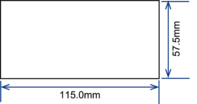
This example describes how to print on material with the dimensions shown in the following figure.
- Register a new jig template.
- Select the job to be printed, then click the [
 ] icon to open the [Jig Print] screen.
- Enter a suitable name for the jig template (here we use "MyJig"), then click the [] icon.
- The display automatically switches to the [Jig Definition] tab.

- Set the jig template.
- Enter the size information for the jig mounted on the printer.
The example here describes the procedure for the jig created and mounted with the following dimensions.
The numbers in the figure correspond to the step numbers shown after it.

(1) | Enter the overall jig size. |
|
|
(2) | Enter the distance from the print origin position to the lower right of the jig. |
|
|
(3) | Enter the angle for the jig skew with respect to the table. Enter positive values for counter-clockwise angles and negative values for clockwise angles. |
|
|
(4) | Enter the material size. |
|
|
(5) | Enter the number of materials placed in the width and height directions respectively. |
|
|
(6) | Enter the interval and pitch when laying out materials in rows. |
|
|
(7) | Enter the distance from the lower right of the jig to the lower right of the material position. |
|
|
(8) | Select the job placement reference if the material size does not match the image size. |
|
|


- If the material position is defined within the print margin area (right edge or front edge), any images placed on that material will be cropped.
- Do not define the material position within the print margin area.
- Positions the job on a jig.
- Click the job [
 ] icon to display the [Job List] tab.
- Select the job to be printed, then open the [Jig Print] screen. The example here shows the procedure for selecting three arranged jobs.

- Select the jig template created (MyJig).
- The jobs are placed in the preview one by one.

- If each job is to be printed multiple times, select the job in the preview, then set the number of copies to be printed in [Copy]. Here we set two copies of each job to be printed.

- [Jig Print] cannot be selected if multiple non-arranged jobs are selected. Depending on the conditions, some settings may not allow [Jig Print] to be selected. For more information, refer to Conditions.
- Placement proceeds from the upper jobs. If the printing sequence is important, note the sequence in which images are imported into RasterLink7.
(The order of the job list is determined automatically by the order in which images are imported. The job list cannot be reordered after images have been imported.)
- Print.
Click the [] icon below the preview to print.
Corrective action when printing issues arise
When the print position is offset
If the print position is offset even when the previously set jig template is called up and printing is repeated, set [Adjustment] on the [Jig Definition] tab.
In the example described here, the third material position is offset.
- Measure the amount of offset between printing and the material.

- Opens the [Jig Print] screen.
- Open the [Jig Definition] tab.
- Select [Material 3] in [Adjustment], then enter [Width] and [Height] as shown below.

- Print again and check the position.
Print only a specific job when one material is not correctly printed
(when copy is set with only one job)
- Set the number of copies to the number of failed prints.
- Print.
Print only a specific job when one material is not correctly printed
(when using arrangement)
- Cancel arrangement.
- Repeat arrangement for only the job that was incorrectly printed.
- Print.
Import a jig definition file to RasterLink7
Import a jig definition file created as described in .
- Click the [
 ] (Import) icon.
- A file selection dialog appears.
- Select the required jig definition file, then click [OK].
- The jig template set by the definition file will now be selected.
- When a jig template with the same name already exists in RasterLink7
- When the selected definition file size exceeds the table size of the printer displayed in RasterLink7.
- When the exported jig definition file has been renamed
When exporting a jig definition file
- Select the jig template to be exported.
- Click the [
 ] (Export) icon.
- The file save dialog appears.
- Add a suitable name, then click [Save].
- The name specified here will be used as the name of the jig template when the jig definition file is imported to RasterLink7.