Tiling - Operations
Start tiling setting
- Select the [Tiling Edit] check box on the [Divide Edit] tab.
- This allows the various [Tiling] function settings to be edited.
Enlarge or reduce a tiling job
- Select the [Valid] check box in [Scale].
- Sets [Scan] and [Feed] for the job to be printed.
- [Scan] and [Feed] can be set as ratios (%) or size.
- If the [Keep aspect ratio] check box is selected, jobs can be enlarged or reduced while retaining the aspect ratio of the original image.
Rotate a tiling job
- Select the angle for counter-clockwise rotation in [Rotation].
Reverse a tiling job
- Select the [Reverse] check box in [Mirror].
Set the output range for the work
- Set the [Scan] and [Feed] for [Size] in [Work].
- Set the [Scan] and [Feed] for [Lower Right Corner].
- The lower right reference point of the work is updated.
- The range of the output work is indicated by red lines in the preview.

- Clicking [Whole Image] resets the settings.
Divide the work into tiles
Divide by setting tile size
- Set the [Scan] and [Feed] for [Tile size] in [Divide tile].
- Click [Apply to All Tiles].
- The work is divided based on the lower right reference point.
Divide by setting number of tiles
- Set the value for [Width] for [Tile quantity] in [Divide tile].
- Set the value for [Feed] for [Tile quantity].
- The work is divided equally into identical size tiles.
Setting tile size individually
Use the [Right], [Left], [Top], and [Bottom] buttons to select the required tile and specify the size.
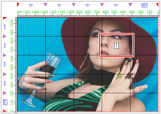
The size of a selected tile is displayed in the preview in boxes as shown below.
Clicking a ▼ symbol selects it (changing to ▽) and allows fine adjustment using the cursor keys.
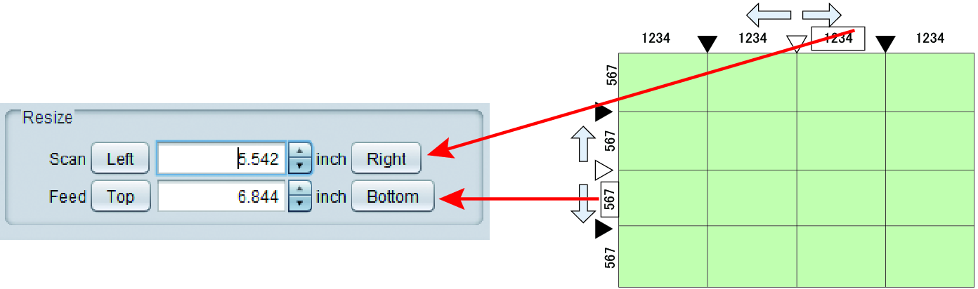

- Set each tile to a size at least 25.4 mm per side.
Tiles less than 25.4 mm in size may be created at the top edge or left edge of the work.
In such cases, increase the size of the tiles adjoining the top edge or left edge using [Resize]. - If tiles measuring 25.4 mm or less are present, a warning message will appear when printing or switching between screens, and processing will be aborted.

Set overlap
When producing signs, gaps may result when tiled images are pasted unmodified.
Overlaps can therefore be set for areas between adjacent tiles to prevent this.
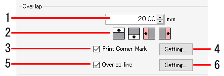
- Enter the overlap length in the numerical input box (1 in the figure above) in [Overlap].
- Click the required overlap position selection icons (top, bottom, left, and right icons, 2 in the figure above).
- The clicked icons change color.
- The following figure shows an example with the work divided into three widthwise. The overlap will be set as shown below (overlap indicated by shaded areas) if the "Left" and "Right" overlap position selection icons are clicked.

- If you wish to print marks for aligning the tiles after printing, select the [Print Corner Mark] check box (3 in the figure above).
- The [Corner mark settings] dialog appears when the [Setup] button (4 in the figure above) is clicked.

[Corner mark settings] dialog | |||
| [Position and Length] | : | Sets the line length (0 mm to 100 mm) for the + marks. (The locations of the lines in the + marks currently being edited in the dialog for which the length is being changed are indicated in red.) |
[Line Width] | : | Sets the line width (0.3 pt to 30 pt) for the + marks. This can be set in 0.1 pt increments. | |
[Color] | : | Sets the line color and density for the + marks. | |

- Clicking [OK] applies the settings.
- If you wish to print lines at the boundaries between the tile body and the overlap, select the [Overlap line] check box (5 in the figure above).
- The [Overlap line settings] dialog appears when [Setup] (6 in the figure above) is clicked.
[Overlap line settings] dialog | ||||
|
| [Line Width] | : | Sets the line width. This can be set in 0.1 pt increments. |
| [Line Color] | : | Sets the line color. | |
| [Interval Color] | : | Sets the color between lines. | |
| [Dashed line] | : | Selecting the check box changes lines to dashed lines. The length of dashes and interval between dashes can be set in 1 mm or 0.1 inch increments. | |

- Clicking [OK] applies the settings.

Print tile numbers
Enabling this setting prints the tile numbers to make it easy to determine the position of each printed tile.
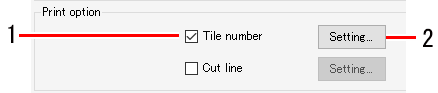
- Select the [Tile number] check box in [Option].
- The [Tile number settings] dialog appears when [Setup] is clicked.
[Tile number settings] dialog | ||||
|
| [Size] | : | Sets the font size for the tile numbers to be printed. (10 to 120 points) |
| [Line Color] | : | Sets the color for the tile numbers to be printed. | |
| [Position] | : | Sets the position at which tile numbers will be printed. | |
| [Print tile number on the overlap] | : | Selecting the check box prints tile numbers on the overlaps. | |

- Clicking [OK] applies the settings.
- The tile numbers are indicated with W for the scan direction and H for the feed direction, with the tile at the bottom right (print origin) numbered (1,1).

Print cut lines
Enabling this setting prints cut lines around the tiles. This can be used as a guide for cutting when tiles have white areas.
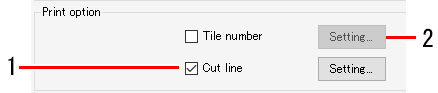
- Select the [Cut line] check box in [Option].
- The [Cut line settings] dialog appears when the [Setup] button is clicked.
[Cut line settings] dialog | ||||
|
| [Line Width] | : | Sets the line width. This can be set in 0.1 pt increments. |
| [Line Color] | : | Sets the line color. | |
| [Interval Color] | : | Sets the color between lines. | |
| [Dashed line] | : | Selecting the check box changes lines to dashed lines. The length of dashes and interval between dashes can be set in 1 mm or 0.1 inch increments. | |

- Clicking [OK] applies the settings.
- Cut lines are printed on the perimeter of the tiles including the overlaps.
Set the tile printing order
Print all tiles
- Click the [
 ] icon for [All tiles] in [Print Order].

Print specified tiles
- Select [Selected tiles in [Print Order].
- Numbers are displayed on the tiles in the preview indicating the print order.

- Click [Clear Order].
- This removes the numbers from the preview.
- Click the tiles to be printed in the preview.
- Numbers are displayed on the tiles clicked indicating the print order.
- The print order is determined by the order in which the tiles are clicked.
- Clicking [Clear Order] resets the print order specified.
Reverse tiles in even columns
Slight color differences may occur between the left and right sides of the printer due to uneven heater temperature.
This may result in the border sections of adjacent tiles standing out when the tiles are pasted together.
In such cases, print by reversing the tiles in even columns.
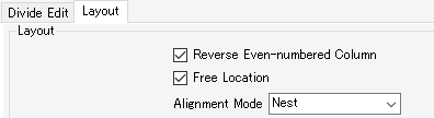
- Select the [Reverse Even-numbered Column] check box in [Placement] on the [Layout] tab.
- [Reverse Even-numbered Column] unselected: All tiles are printed with the same orientation.

- [Reverse Even-numbered Column] selected: Tiles in even-numbered columns (tile B in this example) are rotated by 180° before printing.

Position in desired locations
- Select the [Free Location] check box in [Placement] on the [Layout] tab.
- Select [Alignment Mode].
- [Nest]: Places tiles side by side widthwise.

- [Sequential]: Places tiles side by side in the feed direction.

- Set [Scan margin] and [Feed margin].
- Click [Rearrange].
- Selecting the [Arrange in the Center] check box positions for all of the tiles in the center of the media.
- Tiles can be positioned as desired by dragging them on the preview.
Move specified tiles
- Select the tile to be moved in the preview.
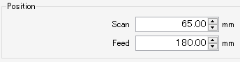
- Set the values for [Scan] and [Feed] in [Move] on the [Layout] tab.
- The tile is moved accordingly.
- Click the [
 ] icon in the preview.
- This starts ripping and printing using the same settings as the last time [Execute] was used.
For more information on settings, refer to Execute.