Print Condition - Operations
Select a device profile
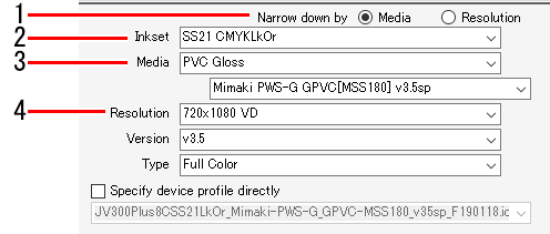
- Select either [Media] or [Resolution] for [Narrow down by] in the device profile on the [Print Quality] tab.
- Selecting [Media] allows device profiles to be filtered in the following order.
Inkset ⇒ Media type ⇒ Media name ⇒ Resolution
- Selecting [Resolution] allows device profiles to be filtered in the following order.
Inkset ⇒ Resolution ⇒ Media type ⇒ Media name
- Select the ink set used from the [Inkset] list.
- Select the media type in the upper box and the media name in the lower box for [Media].

- The media type is classified based on the information registered in the device profile. However, [Others] is displayed for the media type in device profiles that do not include this information.
- Selecting [All] for media type allows all of the media to be selected by media name.
- If the media name displays [Base clear], [Base primer], [High-speed primer], [LD1], [LD2], or [LD3], special conditions apply. For more information on how to use, refer to Special Conditions.
- Select the output resolution from the [Resolution] list.
- Higher resolution gives higher quality but reduces the printing speed. Lower resolution increases the printing speed, but results in lower quality. Select to suit your requirements.
- [Version] displays the version of the selected device profile.
- [Type] displays the type of the selected device profile.
- The print quality and speed will vary depending on Select the output settings.
- Selecting the [Specify device profile directly] check box allows the device profile to be selected using the file name without filtering.
Select the output settings
- In this manual, the maximum feed width that can be printed per scan is called "one band".
- The values set for the device profile settings are indicated by [(Default)].
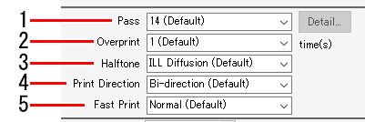
- Select the number of passes (number of divisions per band) from the [Pass] list in [Output Resolution] on the [Print Quality] tab.
- A larger number of passes increases the quality but reduces the printing speed.
- The following [Pass quality setting] dialog appears when [Details] is clicked.
Moving the slider to the right increases the quality but reduces the printing speed.
Clicking [OK] applies the settings.

- Set the number of scans for each printed pass in [Overprint].
- Increasing the number of scans increases the print density.
- Select the gradation printing method from the [Halftone] list.
- Select from the [Print Direction] list.
- [Uni-direction]: Prints only when the print head moves from right to left.
This increases the quality compared to [Bi-direction] but reduces the printing speed.
- [Bi-direction]: Prints when the print head moves both left and right.
This reduces the quality compared to [Uni-direction] but increases the printing speed.
- The [Bi-direction] option may not be available with certain models.
- Select [ON] or [OFF] from the [Fast Print] list.
- Selecting [ON] reduces the quality but increases the printing speed.
- The [Fast Print] option may not be available with certain models depending on the resolution.
Explanation of output setting items
- [Pause Time per Scan]
Sets the time for which the head pauses after each scan.
Use ink dryness as a guideline to help you decide this setting. - [Drying time after printing]
Sets the amount of time (ink drying time) after one file is printed until printing of the next file begins. - [Cut Media after Print]
Cuts the media after printing and separates it from the roll.
- For Print & Cut jobs, media is not separated from the roll after printing even if [Cut Media after Print] is selected.
- [Leading Margin], [Trailing Margin]
Sets margins before and after printing.
- Besides the margins set here, the printer also automatically adds margins.
- [Feed tail space]
Sets whether to feed the media past blank portions if there are blank spaces after images (at the top of the original image). - [Heater OFF]
Sets the heater off status after printing is complete. - [Vacuum]
Sets the media vacuum strength. If media tends to adhere to the printer too much, set the vacuum setting to low. - [Top Blower]
Sets the top blower status. - [Print Pinch Roller Pressure]
Sets the pinch roller pressure during printing. - [Device Adjust Parameter] screen
- Post-heater/Fan-heater/Preheater/Print-heater
Sets various heater settings.
Click [Apply to printer] to send all temperature settings to the printer.
By setting the temperature before printing, you can reduce the heater temperature adjustment time immediately before printing.
If both Post Heater 1 and Post Heater 2 are present, Post Heater 1 cannot be set to a higher temperature than Post Heater 2. If the set temperature for Post Heater 1 is higher than that Post Heater 2, the temperature will be unified to the temperature of Post Heater 2. - [Media Feed Speed]
Sets the media feed speed value if accurate feeding is not possible under the default media feed speed. - [Feed Correction]
Corrects the media feeding amount if banding appears on printed images when roll media is printed while it is fed forward.
Print a color pattern (with a roll-to-roll printer)
Color patterns are printed for checking nozzle clogging.
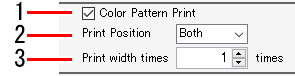
- Select the [Color Pattern Print] check box.
- Select the position for printing the color pattern from the [Print Position] list.
- [Left Side]: Prints a color pattern on the left edge of the media.
- [Right Side]: Prints a color pattern from the print origin.
- [Both]: Prints color patterns on both the print origin and the right and left edges of the media.
- Set the print width for the color pattern to be printed on the left side using [Print width times].
- Set in a range of 1 to 5 times.
- The color pattern print width per nozzle is 1.8 mm.
- The amount of ink consumption displayed after RIP and print does not include the ink amount consumed to print a Color pattern.
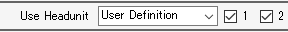
Select a head unit to use for printing
- Select the head unit to be used for printing in the [Use Headunit] list.
Correct the feed and scan direction distance (with flatbed printers, hybrid printers: rigid)
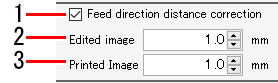
- Select the [Feed direction distance correction] check box.
- Enter the feed direction distance for the data to be printed in [Edited image size].
- Enter the feed direction distance (actual distance) prior to distance correction in [Printed Image Size].
- The feed direction print size, movement, and copy margins are corrected.
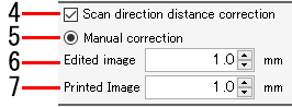
- Select the [Scan direction distance correction] check box.
- Select [Manual correction].
- Enter the scan direction distance for the data to be printed in [Edited image size].
- Enter the scan direction distance (actual distance) prior to distance correction in [Printed Image Size].
- The scan direction print size, movement, and copy margins are corrected.
- [Auto correction] is available on the following models.
· JFX600
· JFX200EX
Selecting [Auto correction] prints using correction values stored on the printer. - When using a hybrid type printer, setting a distance correction value when printing on roll media may not produce the expected results. Use this function when printing on rigid (board) media.
Printing white at higher density
Alters the white ink level and ink limit to increase the density of the white ink printed.
- This operation is useful when the actual white ink density printed is insufficient even when the ink level and ink limit has been set in [Color Adjustment].
- Select the [Printing of the White ink at higher density] check box.

Printing special ink at recommended density
When this setting is turned on in an environment using a special ink, the ink is output at the recommended density.
Example: When the recommended ink density is 70%, the special job is printed at the following density.
- Special job created at 100%: 100% x 70% = 70%
- Special job created at 50%: 50% x 70% = 35%
- It is recommended to turn on this function for printing operation (default setting: ON).
- Turn on (or off) the [To print a Primer at the recommended density], [To print a white at the recommended density], or [To print a Clear at the recommended density] check box according to the color of the special ink used.

Printing Using LamiFit Mode
Fill ink gaps with clear ink to reduce silvering during lamination.
- Select the check box.

- Print with clear ink filled in the gaps of the color image.
Set calibration
Calibration data can be set using either of the following two methods:
- Using RasterLink7 [Calibration] function
- Using Mimaki "MimakiProfileMaster3" profile creation software (available separately)
- Click [Setup] in [Calibration] within the device profile.
- A dialog appears.
- Select the following items.
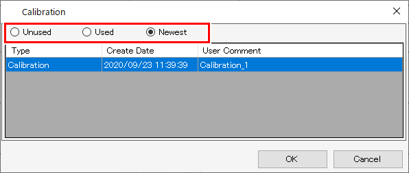
| : | Color matching is performed without using calibration or equalization data. |
| : | Uses calibration or equalization data selected from the list underneath. |
| : | Uses calibration or equalization data with the most recent creation date. The newest data is always selected, so there is no need to reselect the data each time, even when information is added frequently. |
Make small characters clear
- Select the [Edge Optimizer] check box, then select [Edge Optimizer Level] (1-4).
- A higher level gives sharper printing.
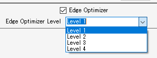
- [Edge Optimizer] is also useful when printing small characters.
- This is also applied to images and illustrations.
- [Step & Repeat]
- [Tiling]
- Jobs with register marks in FineCut
Set the media thickness
Setting the thickness automatically adjusts the printer table height for printing.
- Select [Panel Setting] or [User Definition] in the [Media Thickness] tab.
- Selecting [User Definition] allows the media thickness to be specified.

- [Enable image data overprint setting]
Sets whether to print with the image data overprint setting enabled.
- [Curve Smoothing Rendering]
Sets whether to render curves in image data more smoothly.
- [Renders pattern object with TilingType: 2 (no distortion)
Renders pattern objects as they appear in the design software preview.
Pattern objects are printed offset
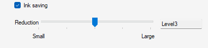
Print with reduced ink consumption
The ink consumption can be reduced compared to when using the same device profile unmodified.
- A device profile version v3.4 or earlier
- An emulation profile
- A 2.5D Texture Maker profile or special-purpose profile such as for print bottom clear
- Entire jobs created using special plates
- Entire jobs with single color replacement
- Entire jobs with [Valid] turned off for the color matching settings
- Objects with CMYK retention specified in the color matching settings
- Colors with color replacement set in [Color Replacement]
- Select the [Ink saving] check box.
- Set [Level].
The effects of levels on color will be as follows:
- Level 1
Ink consumption is reduced without altering the original ink mixture composition as much as possible, maintaining the overall color uniformly. - Levels 2 to 5
Areas consisting of mixtures of CMY are replaced with black ink.
Increasing the level reduces ink consumption by narrowing the reproduction color space.
Perform color matching
In RasterLink7, adjusting the colors actually printed to match the data colors is referred to as color matching.
Colors can be matched based on the ICC profile and unique data.
- In RasterLink7, vector data is referred to as "illustrations", and raster data is referred to as "images".
- In RasterLink7, color matching can be set differently for vector data and raster data.
However, if effects such as blurring and transparency are added to vector data in Adobe Illustrator, some of the objects will be converted to raster data. Applying color matching to objects like this will result in color differences within the same object. In order to prevent this, the vector data and raster data color matching settings should be set identically for objects that use effects such as blurring and transparency.
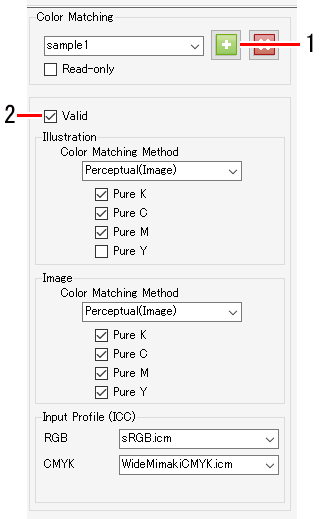
- Enter a suitable name in [Color Matching], then click the [
 ] icon.
- New settings are created.
- Select the [Valid] check box to apply the various settings.
- The settings are divided into [Illustration] and [Image].
- The [Illustration] settings are applied to vector data.
- The [Image] settings are applied to raster data.
[Color Matching Method]
[Perceptual(Image)] | : | Suited for photographs. Color matching is performed to ensure that the overall brightness of the job is close to that of the input images. | |
[Saturation(Graphics)] | : | Suited for illustration images. Color matching is performed to increase the overall density of the job. | |
[Relative] | : | Color matching is performed to ensure that colors within the same color gamuts for the input profile and the device profile are as close as possible. | |
- With [Relative], colors outside the device profile color gamut will be assimilated into the colors of color gamuts that can be represented by the device profile even when the colors can be represented by the input profile.
This results in blowing-out of high-saturation parts.
[Absolute] | : | The color matching method is the same as for [Relative]. Colors including the media color are corrected to ensure they are close to the colors of the input profile. | |
[Gray Balance] | : | These are useful when the original image data uses CMYK color mode. | |
[Relative(BPC)] | : | The color matching method is the same as for [Relative]. Performs black point compensation to improve shadow gradations. | |
[Pure K], [Pure C], [Pure M], [Pure Y]
- These are useful when the original image data uses CMYK color mode. Color matching using an ICC profile may result in color mixing when printing, even when the colors in the original image data have been set as C, M, Y, or K mono colors. Selecting each check box allows printing without color mixing occurring if C, M, Y, or K mono colors have been set.
[Input Profile (ICC)]
- Sets the input profile. Profile Manager can be used to install a target profile if available.
- If a profile is embedded in the original image data, the [Embedded Profile] check box is displayed. Selecting this check box uses the embedded profile preferentially as the input profile.
Adjust ink levels
Adjust the ink levels after color matching processing on the [Color Adjustment] tab.
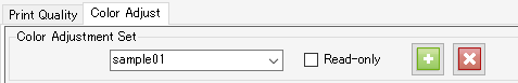
- Enter a suitable name in [Color Adjustment Set] on the [Color Adjustment] tab, then click the [] icon.
- [Color Adjustment] is dependent on the device profile.
A registered [Color Adjustment Set] will not be displayed if a different device profile is selected.
Even if the [Color Adjustment Set] name is the same, it will be treated as a different adjustment file if the device profiles differ. Take care when naming files. - [Color Adjustment] cannot be edited if [Standard] is selected.
- The number of color adjustment sets that can be created is up to 300 for all printer settings registered in RasterLink7.
- Set the density.
- The ink levels can be adjusted for special inks such as white and silver in addition to CMYK inks.
[Whole]
- This alters the ink limits set in the device profile by the same ratio for each ink. This is useful if the overall ink is too dense or too thin. The ink limits are altered by the factors set here. Settings between +1% and 50% increase the ink, but the ultimate ink limit cannot exceed 100%.
Example: When the cyan ink limit is set to 70% in the device profile
[Whole] value | Cyan ink limit |
-50% | 35%: (70% x (100 - 50)% = 35%) |
-10% | 63%: (70% x (100 - 10)% = 63%) |
+40% | 98%: (70% x (100 + +40)% = 98%) |
+50% | 100%: (70% x (100 + 50)% = 105%)
|
[Illustration]
- Sets the ink densities used with vector data.
- The following setting methods are available.
[Contrast] Alters the contrast in a range of -50% to +50%. | -50% to -1% +1% to +50% | |
[Black] Alters the black ink and cyan/magenta/yellow ink levels in a range of -50% to +50%. Use K-CMY adjustment if you require more detailed settings. | -50% to -1% 0% +1% to +50% | |
[Cyan] [Magenta] [Yellow] Alters the cyan/magenta/yellow ink levels in a range of -50% to +50%. This is useful when adjusting hue. The ink levels are changed for middle parts, but the ink limits cannot be changed. | [Highlight] [Middle] [Shadow] | |
[Image]
- Sets the ink densities used with raster data.
- The setting methods are the same as for [Illustration].
[Special Color]
- Sets the ink densities used with special colors.
Alters the special color ink level in a range of -50% to +50%. The ink limit cannot be changed. Special color density adjustment is available when using v3.3 profiles or later.
Fine adjust colors
Clicking [Setup] allows detailed settings for ink limits, linearization, special color ink limits, and adjusting K-CMY mixing ratio.
- [Ink Limit]
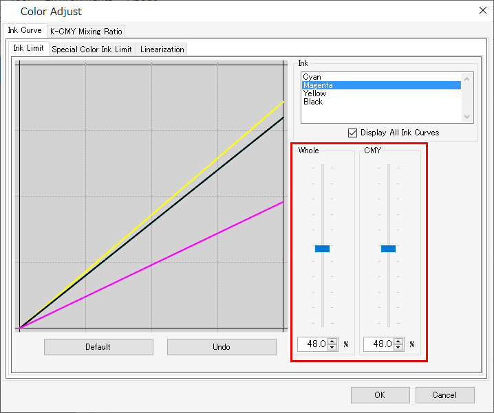
Adjust the ink limit sliders for each of the process color inks (cyan, magenta, yellow, black. etc.). [Whole] sets the ink limits for each color. [CMY] is the ink limit used when three or more inks are mixed together. The overall ink limit forms the CMY color ink limit.
This setting can be used to limit the ink if ink bleeds in areas where three or more colors intermix.

C0,M0,Y0 Using the respective overall cyan, magenta, and yellow limits
C1,M1,Y1 Using the respective 3-dimensional cyan, magenta, and yellow limits
- [Linearization]
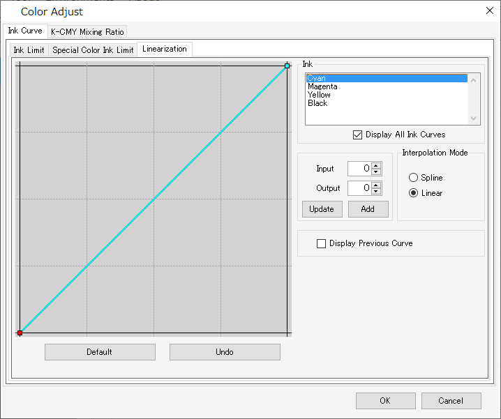
Edit the middle tone density curves for each of the process color inks (cyan, magenta, yellow, black. etc.).
This adjusts the tones to ensure smooth gradations are printed for each ink.
The maximum density (ink limit) can also be altered here, but this should not be changed, as this makes ink limit adjustment more difficult.
- [Special Color Ink Limit]
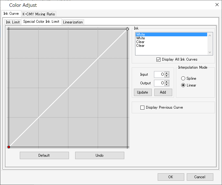
Adjust the densities for special color inks such as white, clear, and silver.
Initially, the densities set in [Input] are used, but the curves should be adjusted on this screen if there is insufficient variation in the middle tone densities, such as in gradations.
- [Enable K-CMY Mixing Ratio]
Alter the curves for the black, cyan, magenta, and yellow usage ratios. Changes can be made for illustrations and images respectively. When the input data is RGB mode, and when excessive ink tends to be used in shadow areas, this adjustment can reduce the amounts of cyan, magenta, and yellow used and increase the black, without changing the shadow tone appearance significantly.
- This setting cannot be used unless black is set to 0% for [Density] on the [Color Adjustment] tab.


