General Print - Operations
Enlarge and reduce jobs
- Set [Scan] and [Feed] for the job to be printed for [Scale] on the [Image Edit] tab.
- [Scan] and [Feed] can be set as ratios (%) or size.
- Selecting the [Keep aspect ratio] check box enables jobs to be enlarged or reduced while retaining the aspect ratio of the original image.
Rotate jobs
- Select [Rotation] on the [Image Edit] tab.
- This allows the angle of counter-clockwise rotation to be set.
- Select one of the following angles.

Reverse jobs
- Select the [Reverse] check box in [Mirror] on the [Image Edit] tab.

- With 0° rotation

- With 90° rotation

Deskew
Deskew (manual input)
This is used when printing skewed media or material positioned at an angle to the table.

- It cannot be used in combination with [Variable Edit].
- [Deskew] on the [Image Edit] tab is used to set the job angle.
- This can be set in the range of -45° to +45°.
- This can be set in conjunction with [Rotation].
- If [Deskew] is applied, the right-hand and lower positions of the job after skewing will be the same as before skewing.

- The [Rotation] and [Deskew] angles are applied in the counter-clockwise direction.

- In the case of arranged jobs, the skew angle can be set individually for each job.
- If there are two or more copies or if a job spans several pages, all jobs will be skewed with the same angle.
- The register marks set in [Register Mark] cannot be skewed.
Register marks will be added to the image rectangle after the job has been skewed.
- The information set in [Printed Information Label] cannot be skewed.
- If [Crop] Crop has been set, the job will be skewed after cropping.
- The [Deskew] value will be disabled if [Tiling] or [Step & Repeat] is set after [Deskew] has been set in [General Print].
- Skewing jobs will cause outlines and straight lines to become slightly jagged.
Jagged edges will become particularly noticeable when the original image is raster data with low resolution.
When the original image is raster data, data should be created using a resolution close to the print resolution.
Auto deskew (UJV100Plus)

- [Auto deskew]
- This setting is available when the pull-back printing setting is enabled in the [Composite] function. Overlay print by pulling back the media (with CJV300, CJV150, CJV300 Plus, UCJV300, UCJV330, and UJV100 Plus)
- When the check box is on, a detection register mark is printed on the first image to be printed, and after the media is pulled back, that register mark is imported to automatically deskew the image and the next print will be performed.
- [Fill around the register marks]
- The areas around the register marks can be filled in using red. This enables the register marks to be detected if they cannot be correctly detected on media whose background color is not white.
Move jobs
Drag and move jobs
- Select a job to be moved in the preview.
- Drag the job to the desired position.

- The origin position of the job is displayed in [Scan] and [Feed].
Set the job origin position
- Set [Scan] and [Feed] for [Move] on the [Image Edit] tab.
- The origin position of the job is moved by the [Scan] and [Feed] size set here.
Position a job in the center of the media
- Select the [Arrange in the Center] check box for [Move] on the [Image Edit] tab.
- If the job has been copied or arranged, the entire area will be positioned in the center of the media in the same way as in Arrange in the center of the media..
Move a job to the trimming origin position (With flatbed printers)
- Select the [Lock the trimming position] check box for [Move] on the [Image Edit] tab.
- The trimming origin position is locked in the display.
- Arranged jobs
- Multi-page jobs
- When [Arrange in the Center] is enabled
- When two or more copies are set
- When register marks are printed
- Print cut lines
- When using jig printing
- When using tiling
- When using step & repeat printing
- When using Kebab jig printing
Copy a job
Copy a job
- Select the number of copies to be made using [Copy] on the [Image Edit] tab.
- The job is copied and automatically positioned.
- Block move: Allows all of the copied images to be moved together.
- Each move: Allows the copied images to be moved individually.
- If [Specify the number of copies in the scan direction] is selected when [Block move] is selected, the layout will wrap based on the specified number of copies.
Move all copied jobs
- Select the number of copies required using [Copy] on the [Image Edit] tab.
- Select [Block move].
- Set [Scan] and [Feed] for [Move] on the [Image Edit] tab. Images can also be moved by dragging on the preview.
- All the copied jobs are moved by the [Scan] and [Feed] size set here.
- With arranged jobs, the move method selection is not displayed, and is set to [Each move].
Jobs should be selected then copied or moved individually. - For multi-page jobs, the number of copies applies to all pages.
A different number of copies cannot be set for individual pages. - Jobs set to [Variable Edit] cannot be copied.
- The maximum number of prints that can be made at once is 4000, including all layers.
Example:
·In a single-layer job, 40 copies with 100 arranged jobs can be printed, which makes 4000 prints possible.
·In a two-layer composite job, 20 copies with 100 arranged jobs can be printed, which makes 2000 prints possible.
Move a copied job individually
- Select the number of copies to be made using [Copy] on the [Image Edit] tab.
- Select a job to be moved in the preview.
- Select [Each move].
- Set [Scan] and [Feed] for [Move] on the [Image Edit] tab. Images can also be moved by dragging on the preview.
- Only the selected job is moved by the [Scan] and [Feed] size set here.
- [Block move]: Moves entire pages.
- [Each move]: Moves only selected pages.
Set margin between jobs
Layout can be specified as [Space] or [Pitch].
Set margin between jobs
- Select [Space] for [Layout] on the [Image Edit] tab.
- Enter the necessary values for [Scan] and [Feed].
- Select the optimization for the preview, then click the [
 ] icon.
- The job is rearranged using the new margin settings. Check the results on the preview.
- The margins set using the [Arrange] function will be overwritten by the operation in Step 3.

Set the distance from a job origin to the next job origin
- Select [Pitch] for [Layout] on the [Image Edit] tab.
- Enter the necessary values for [Scan] and [Feed].
- Select the optimization for the preview, then click the [] icon.
- The job is rearranged using the new margin settings. Check the results on the preview.

- With arranged jobs
- With multi-page jobs
Position multiple pages side by side widthwise
- Select [Each move] for [Copy] on the [Image Edit] tab.
- Specify the required margins using [Layout].
- Click the [] icon.
- The multiple pages are rearranged using the new margin settings. Check the results on the preview.
- When moving blocks, pages will be positioned vertically.
Set the printing pages
Set the printing pages
- With multi-page jobs, [Printing range] items are displayed.
- Set one of the following for [Printing page range] on the [Image Edit] tab.
[All] | : | Prints all of the pages for multi-page jobs. |
[Page specification] | : | Prints those pages set. |
Setting example: |
| |
To print pages 2 to 5 | : | [2-5] |
To print pages 2, 4 and 6 | : | [2,4,6] |
To print pages 2 to 5 and pages 8 and 11 | : | [2-5,8,11] |
Set form-feeding
- The [FF(Form-feed)] item appears in the following cases:
- When the job is a multi-page job
- When the printer is not a flatbed printer - This setting is available when [Copy] is set to [Block move] on the [Image Edit] tab.

- On the [Image Edit] tab, select one of the following options for [FF (Form-feed)].

[Not inserted] | : | Sends form-feed code at the end. |
[Insert at page break] | : | Sends form-feed code for each page. |
[Insert at line break] | : | Sends form-feed code for each line. |

When [Cut after Print] is selected on the [Print Condition] screen, media is cut on the basis of form-feed code.
Set the print area (with flatbed printers)
- Registering a valid print area provides a guide when positioning images. It also prevents printing outside the range of the media.
- Enter the name of the new print area template to be set in the text input box for [Print Area] on the [Image Edit] tab.
- Click the [
 ] icon.
- The new template will be registered.
- Click [Setup].
- The [Print Area] dialog appears.

- Print area preview
The valid print area set on the [Valid Print Area] tab is indicated by a red rectangle.
- [Valid Print Area] tab
- Set the following items.

| : | Sets the valid print area to the maximum size and sets the origin position at the default origin position for the printer. |
| : | Enter the width of the valid print area. |
| : | Enter the feed for the valid print area. |
| : | Enter the offset distance from the printer origin in the width direction. |
| : | Enter the offset distance from the printer origin in the feed direction. |
Set register marks
- Multi-page jobs cannot be added register mark.
- [Register Mark] on the [Image Edit] tab is used to set the register marks added to jobs.
Register marks are used to detect the cutting positions. Set the mark shape to suit the settings for the printer and cutting plotter.

- [Mark Shape]
The following mark shapes can be selected. Select [OFF] if you do not wish to add register marks.

Zero margin register marks
- This function can be used with the following printers:
CJV300, CV150, UCJV300, CJV300 Plus, CJV330, UCJV330
Using zero margin register marks allows the amount of media used in printing & cutting to be reduced compared to the Type 1 or Type 2 marks. Zero margin register marks can be set as follows.
- Set the following conditions on the [General Print] screen.
- Set [Copy] to a number greater than one.
- Select [Block move] for the copy move method.
- Select [
 ] (Type 1) or [
 ] (Type 2) for the register mark shape.
- Select [Individual] for the register mark position. [
 ] (zero margin register mark) is now available for selection.
- Select [] (zero margin register mark) for the register mark shape.

Square register marks
These cannot be used with printing and cutting machines.
- [Size], [Line Width]
The register mark size can be altered. [Use recommendation Crop mark size] indicates the recommended size to ensure detection using Mimaki printers and cutting plotters. Enter a value greater than this.

- The value for [Use recommendation Crop mark size] will vary depending on the job size.
- Add print direction mark
This adds a ▼ symbol when the register mark is printed. Adding this mark ensures that printed media is fed into the printer in the correct direction when working with jobs that make it difficult to identify the direction.

- This function can be used with the following printers:
CJV300, CV150, UCJV300, CJV300 Plus, CJV330, UCJV330
- When zero margin register mark is selected for [Shape] in [Register Mark]
- When an intermediate register mark is selected for [Shape] in [Register Mark]
- When the separation between register marks is less than 20 mm
- When the ID cut function is enabled
- With arranged jobs
- The print direction mark function cannot be registered as a favorite.
- When a job is rotated, the position of the print direction marks is moved to match the rotation.
- The size of the print direction marks does not change even when the register mark size or scale is changed.
- [Fill around the register marks]
The areas around the register marks can be filled in using red. This enables the register marks to be detected if they cannot be correctly detected on media whose background color is not white. It is also effective for ID cutting.

- If using a model equipped with white ink, set the [Fill color] to "White" in the [Color Settings] screen.
If registration marks cannot be recognized even when filled with red, specify white ink.
It also applies to ID cutting.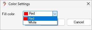
- [Layout]
This allows you to select whether register marks are added to each individual job or to the overall layout on which multiple jobs are positioned.
[Individual] | : | Adds register marks for each job. This increases the time taken for reading in, as the register marks have to be detected for each job when cutting, but it minimizes any offset between printing and cutting. If [Individual] is selected and register marks are set to be printed for print & cut jobs, a screen appears for setting the register mark detection positions. |

- Increasing the number of register marks to be read in increases the cutting position accuracy, but also increases the time taken.
- The register mark detection positions can be changed between the first time and subsequent times.
- [Tiling]
- [Step & Repeat]
- When multiple copies are set and the number of jobs for the last row is smaller than the number of jobs for the first row
[Whole] | : | Adds register marks for the overall layout of multiple jobs. This reduces the time taken for reading in compared to [Individual], as there are fewer register marks to be detected, but it increases the offset between printing and cutting.
|

- [Tiling]
- [Step & Repeat]
- [Crop]
- When cutting with a Mimaki cutting plotter after printing, add the register marks using FineCut.
- [Intermediate Register Marks]
- This function can be used with the following printers:
CJV300, CV150, UCJV300, CJV300 Plus, CJV330, UCJV330
Intermediate register marks can be added when [Whole] is selected for the register mark placement.
Adding intermediate register marks ensures more accurate cutting with long-length jobs.
[Direction] | : | Sets the orientation of intermediate register marks. |
[Count] | : | Sets the number of intermediate register marks. (The number can be set in a range from 2 to 10.) |
- Set the count to ensure that the register marks are spaced at least 50 mm apart.
- Set the offset to at least the size of the register marks.
- [Offset]
This allows an offset to be set between the register marks and the jobs.
Print cut lines
- Select the [Cut line] check box for [Cut line] on the [Image Edit] tab.
- Click [Setup].
- The [Cut line settings] dialog appears.
- Set the following items.

[Line Width] | : | Set in a range between 0.3 point and 30 points (in 0.1 point increments). |
[Line Color] | : | Set the line color. |
[Interval Color] | : | Set the color between lines. |
[Dashed line] | : | Selecting the check box changes lines to dashed lines. |
[Dashed line style] | : | Set the length of dashes and intervals between dashes in the dashed lines. |
- Selecting the [Cut line] check box displays the output size as the size including the cut lines.
- When [Step & Repeat] is set
- When [Shape] is specified as other than [OFF] in [Register Mark]
- For jobs with register marks output using RasterLink from FineCut
Set Fotoba cut marks
- Select the [Add fotoba cut mark] check box for [Fotoba cut mark] on the [Image Edit] tab.
- Click [Detail].
- The [Fotoba cut mark print settings] dialog appears.
- Set the following items.

[Mark Shape] | : | Sets the marks between jobs. Select [ |
[Horizontal mark width] | : | Select the width of the marks in the scan direction. |
[Line Width] | : | Set in a range from 1.0 mm to 3.0 mm. |
[Line Spacing] | : | Set the spacing between the double lines in a range from 1.0 mm to 3.0 mm. |
[Margin] | : | Set the margins between jobs and marks. |
[Between Jobs] | : | The margins between jobs can be set if [ |
[Layout] | : | Select the job placement position. |
[Offset] | : | This allows the distance to the mark from the right-hand edge to be set when [Right] is selected, and the distance to the mark from the left-hand edge to be set when [Left] is selected. |
 ] if you do not wish to print vertical marks between jobs, select [
 ] if you wish to print vertical marks between jobs, and select [
 ] if you wish to use double lines for the vertical marks.
- With Print & Cut jobs
- With jobs using twin-roll printing
- With jobs using step & repeat printing
- Special plate job
- With jobs for which any of the following are set on the [General Print] screen
(Register mark shape is not set to [OFF], [Lock the trimming position] is selected, or [Cut line] is selected) - With jobs for which [Print Corner Mark] or [Cut line] is selected from the [Tiling] screen
- With auto execution
- [Target size] displays the size (calculated size) after cutting using a Fotoba Series.
- This can be used in conjunction with the copy, arrangement, and tiling functions.
Set the XY slitter
- This function can be used with the following printers:
JV330, CJV330, UCJV330
Using an XY slitter enables slitting to be performed in-line. Selecting the [XY Slitter Edit] check box and setting the corresponding items prints marks and reference lines for X slitting.
For more information on how to use the printer and RasterLink7, refer to "Using the XY Slitter" in the "330 Series Operation Manual".
- Select the number of copies to be made using [Copy] on the [Image Edit] tab.
- Copying is not necessary when slitting variable print jobs.
- Select the [XY Slitter Edit] check box on the [Image Edit] tab.

- Select the slitting method.

[Slit at the same time as printing] | |
| |
[Slit afterwards] | |
|
|
- The following five types of mark are available, the spacing of which is determined automatically depending on the setting. (Size cannot be altered)
| Mark 1 | Scan: 30 mm | Feed: 1.5 mm |
| Mark 2 | Scan: 30 mm | Feed: 6 mm |
| Mark 3 | Scan: 10 mm | Feed: 10 mm |
| Mark 4 | Scan: 20 mm | Feed: 1.5mm |
| Mark 5 | Scan: 20 mm | Feed: 6 mm |


- Auto Cut on the quality screen
- Auto Cut on the Cut Edit tab
- Rearrangement
- Copy block move
- Fill around the registration marks
- Fotoba cut mark
- Cut Line
- Centering
- Color pattern
- Left/right margin
- Step & Repeat jobs
- Outer Frame Cut
- Print & Cut jobs
・ Can be used only when [Slit afterwards] is selected.
・ ID Cutting can also be specified. However, Print & Cut jobs from FineCut cannot be used together. - Register mark
・ Can be used only when [Slit afterwards] is selected.
・ Zero margin register marks cannot be used when the [XY Slitter Edit] check box is checked.
・ Individual registration marks can be used only when one copy is specified. When two or more copies are specified, only whole register marks can be used. - Pull-back print (UCJV330)
Depending on the top and bottom print bleed settings, marks will be printed on the same line and a detection error will occur when detecting the register mark of the ID cut. Be careful not to overlap the marks.
- Example 1 : When the mark is printed on the same line

- Example 2 : When the mark is not printed on the same line

- Select the Y direction slitting method using [Y Slit].
- The following three slitting methods are available:
[Normal], [Line Space], [None]

Item | [Normal] | [Line Space] | [None] |
|---|---|---|---|
Y slit position | Top and bottom edges of image | Margin (feed)/2*1 | None |
Size | Feed: 297 mm or more Scan: 210 mm or more | Feed: 297 mm or more Scan: 210 mm or more | Feed: 297 mm or more Scan: 210 mm or more |
Margin (feed) | 62 mm or more | 0 mm or more | 0 mm or more |
*1: | If the margin is 10 mm, slitting will be performed leaving a margin of 5 mm above and below the image. All image data will be slit using the same size. |
- Set the margins using [Print Bleed].

Positive value | : | Image data will be slit on the inside according to the size specified. (No border) |
Negative value | : | Image data will be slit on the outside according to the size specified. (Margins added) |
Item | [Normal] | [Line Space] | [None] |
|---|---|---|---|
[Print Bleed] | Top/bottom/left/right | Left/right | Left/right |
- When using white ink to print the marks and X cutter reference lines, select the [XY slitter marks are printed in white] check box.
- This is displayed when white ink has been set in the printer.
- This is used for slitting transparent media.

- Set the quantity of image data to be arranged in the media width direction using [Width Copy Count].
- Up to two copies can be specified. (Four X cutters are required when two copies are specified.)

- Set the scan direction margin between mark and image using [Mark Offset].

- Click [Automatic mark offset setting] to automatically set the offset and position the image data in the center of the media.

- If you set [Automatic mark offset setting] while [Slit afterwards] is selected, a mark will be added to the left edge of the media.
If you increase the number of copies in [Width Copy Count], these marks will exceed the media, so the number of copies cannot be increased as is.
If you want to increase the number of copies, enter 0 in [Mark Offset] and then increase the number of copies in [Width Copy Count].
- To print reference lines for setting the X cutter, click [Print X-Cutter Reference line].

- The [Print X-Cutter Reference line] dialog appears.
- Clicking [OK] prints the X cutter reference lines.

- One copy in the scan direction: Two X reference lines are printed.
- Two copies in the scan direction: Four X reference lines are printed.
- The reference line feed direction size is 545 mm.
- Set the X cutter blade at the position corresponding to the printed X cutter reference line, as instructed on the main unit operation panel.
- Check [X-Cutter Place].

[Cut Line] | [Right] | : | Displays the distance of the image right-hand edge from the right-hand edge of the media. |
| [Left] | : | Displays the distance of the image left-hand edge from the right-hand edge of the media. |
| [Right Margin] | : | The right margin size set for the printer is displayed here. |
|
| : | When the width copy count is set to 2, the left/right buttons can be used to select the column and check the X cutter position. |


- Calculate the X cutter position by adding the right margin size to the X cutter position displayed on the screen.
- Jobs with multiple copies set on the [General Print] window and [Each move] selected
- With composite jobs
- Variable print jobs
- Jobs cropped on the [Crop] window
- Jobs with layout margins specified
- Jobs with move set ([Arrange in the Center] not selected)
- Jobs with a printed information label added
Set information labels
- Select the [Add label] check box for [Information label] on the [Image Edit] tab.
- Select the check box for the information to be added.
- If the "Printed Date" checkbox is checked, the RIP will be executed even if "Print Only" is selected for "Execution".
- Click the [
 ] icon in the preview.
- Ripping/printing starts.
- The processing used for execution can be set in [Option] - [Job Control] ([Option]).