[Option] - Operations
Set job control
- Select the [Job Control] tab in the [Environments] - [Option] dialog.

- Select the [Hyper Job Threading] item.
- This sets whether or not to process multiple jobs simultaneously with a single printer.

| Processes and quantities running in parallel | Processes and quantities running in parallel | Processes and quantities running in parallel |
|---|---|---|---|
[OFF] | Importing image data × 1 | RIP × 1 | Printing × 1 |
[Level 1] | Importing image data × 1 | RIP × 1 Printing × 1 |
- |
[Level 2] | Importing image data × 1 RIP × 1 Printing × 1 |
- |
- |
[Level 3] | Importing image data × 2 RIP × 2 Printing × 1 |
- |
- |
[Level 4] | Importing image data × 3 RIP × 3 Printing × 1 |
- |
- |
[Level 5] | Importing image data × 4 RIP × 4 Printing × 1 |
- |
- |

- Setting the RIP level to 3 or higher and increasing the number of simultaneous RIP processes increases CPU usage and memory consumption during RIP processing.
If a PostScript error occurs at level 3 or higher, set the level to 2 or lower.
Data containing high-resolution raster images, or extensive use of transparent objects and gradient objects, tends to significantly increase CPU usage and consume more memory.
- Specify [RIP Memory Settings] if necessary.
[Specify RIP processing memory usage] | : | This should normally be disabled. When disabled, ripping is performed automatically using the optimum amount of memory. Depending on the image data, memory may be used up to a level where an error occurs. In cases like this, the amount of memory used can be set to ensure successful ripping. |
[Fixing RIP processing band amount] | : | This should normally be disabled. When disabled, the number of lines (bandwidth) for the image data to be processed at a time is calculated automatically depending on the image data, ensuring processing using the optimum number of lines. Depending on the image data, fixing the number of lines may enable ripping to be performed more quickly. If ripping is slow or the image appears to freeze, this setting can be enabled to increase the ripping speed. |
Max CPU threads usage | : | Allows the number of CPU threads used for ripping to be specified. |
- Set [Create information for estimating ink consumption].
- When creating a job, whether or not the data is created for use to calculate the estimated value can be set in Estimate ink consumption.
Selection item | Job creation time | Estimate processing | Accuracy | Remarks |
|---|---|---|---|---|
[Create] | Slow | Fast | Poor |
|
[Automatic] | Slow | Medium | Good | Decision on whether or not to create data depends on the job size and favorite settings. |
[Do not create] | Normal | Slow | Good | Data is not created. When the estimate function is used, calculation uses the original image data. |
- Select or deselect the [Calculate Ink Consumption from riped Data] check box.
- Selecting this calculates the ink consumption values and displays them in Properties.
- Select or deselect the [Notify ink shortage.] check box.
- When either of the following is printed, a warning is displayed indicating insufficient ink for printing based on the calculated value and ink level.
· The [Calculate Ink Consumption from riped Data] check box is selected and the ink consumption has been calculated before printing.
· [Ink Consumption Estimation] has previously been performed.
- Printer name
Select the printer for ink level adjustment.
- Ink level
Adjust the threshold ink level for warnings, as needed.
The default value varies depending on the model.
- Select or deselect the [Lock the job after printing] check box.
- Selecting this displays a lock symbol for the job after printing, preventing the settings for that job from being edited or deleted.
- Select or deselect the [RL6Plus compatible] check box.
- When selected, the processing for the following items will be the same as for RasterLink6Plus.
・ If a flatbed printer is used for composites consisting of continuous special color jobs, these will be combined into separate outputs.
・ When using special color, the same special color over print as RasterLink6Plus is set as the default.
- Change [Number of jobs that can be registered] as necessary.
- Default: 200, maximum: 1,000
Increasing the number of registered jobs increases the amount of image data displayable on the [Job List] tab. However, it also increases the time taken to display the [Job List] tab after starting up RasterLink7.
- Enable or disable [Job execution settings].
- Enabling this displays the option screen settings as the default values on the execute screen.
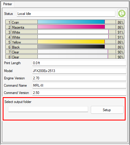
- Specify [Output setting] if necessary.
- [Print to output port] should normally be selected.
This outputs to the output port set when the printer was registered.
- Output for other settings will be as follows depending on the combination of output ports set when the printer was registered:

Output setting | Output port at printer registration | ||
|---|---|---|---|
USB2.0 | Ethernet | File | |
[Print to output port] | USB2.0 | Ethernet | File |
[Output command to setting folder] | Setting folder | Setting folder | Setting folder |
[Output command to configuration folder and print to output port] | Setting folder | Setting folder | Setting folder |
USB2.0 | Ethernet | - | |
- The command is output to the configuration folder with the file name in the format "Date_Time_Jobname.bin".
Example: 20240701_123001_Test job.bin
- The configuration folder is set using [Select output folder] on the printer status screen.
- When using the JFX600-2531, JFX600-2513, or Tiger600-1800TS, the [Output setting] cannot be specified.
- Configure the [Mpc Streaming Settings].
- This setting is displayed when Tiger600 is registered as a printer.
- This setting should not normally be changed. If the carriage stops during printing due to the PC specifications or network environment, try increasing the values.
- Set [Threshold Binary Line].
- This setting should not normally be changed. If the carriage stops during printing due to the PC specifications or network environment, try increasing the values.
- Click [OK].
- Settings that have been changed will be applied after restarting RasterLink7.
Save execution results to a file
Selecting this check box outputs the execution results in CSV format once printing and cutting are complete if a save destination is set.
- File output setting method
- Select the [Save execution result to a file] check box.
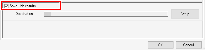
- When initially specifying the save destination, the file save destination selection dialog appears automatically.
In such cases, proceed to Step 3.
- Click [Setup].
- The file save destination selection dialog appears.
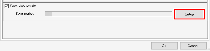
- Select the save destination for the output file, then click [Select].
- Click [OK].
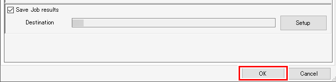
- The following information will be output.
For printing
File name, results, ink consumption results, ripping start time, ripping end time, printing start time, printing end time, number of executions, detailed results
For cutting
File name, results, ink consumption results, cutting pass creation start time, cutting pass creation end time, cutting start time, cutting end time, number of executions, detailed results
Display print length warning
After outputting a specific job, a warning will be displayed when the total print length reaches the specified length. This is displayed and can be set when the following printer is registered:
Printer: UCJV330
- Select the printer to be set from [Printer Name].
- Select or deselect the [After executing 2.5D printing, display warning according to following print length.] check box.
- The print length can be specified when this is selected.

- After launching RasterLink7, the start of 2.5D printing on the printer involved is treated as zero, and the warning is displayed before starting printing that will reach the specified length, regardless of the job type.
- After the warning is displayed, restarting 2.5D printing counts the print length from zero again.
- The print length counter will be reset to zero when RasterLink7 is restarted.
Set the [Execute] icon operation on each function screen
Set the operation performed by clicking [Execute] on the [General Print], [Tiling], and [Step & Repeat] screens.
The settings are configured separately for each printer registered.
- Select the printer to be set from [Printer Name].

- Select the [Apply job execution settings] check box.
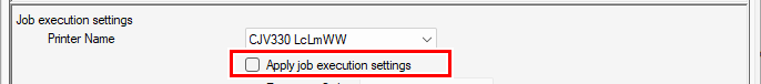
- If this is not selected, the previously used conditions will be used.
- Sets the execution procedure.
- The setting details are the same as for Execute.
Set the display
- Select the [Display] tab in the [Environments] - [Option] dialog.

- Select the display language from the [Language] pull-down menu.
- Set the display language used for RasterLink7.
- Adjust the [Preview Resolution] slider.
- Moving the slider to the right increases the display resolution on the [Preview] window but makes the preview slower.
- Moving the slider to the left reduces the display resolution on the [Preview] window but makes the preview faster.
- Select or deselect the [Display Tooltips] check box.
- When this is selected, simple explanations (tool tips) are displayed for individual items at the mouse cursor position.
- Select [Unit].
- Set the display units for length to mm or inch.
- Select or deselect the [Display print progress] check box.
- If this is selected and connected to the printer,Print progress is displayed during printing. 8. [Print progress] tab
- Select or deselect the [Display job name search function.] check box.
- When this is selected, the job name search input box is displayed.
- The job name search input box enables jobs to be searched. Job Name Search
- Select or deselect the [Use a barcode reader.] check box.
- Selecting this allows search parameters created as barcodes using standard barcode conversion software to be imported to RasterLink7. Search Using a Barcode Reader
- Set the movement when image data for which spot colors are specified is loaded.
[Run when less than] | : | The spot color information is analyzed when the number of spot colors within the image data is smaller than the value set. |
[Run always] | : | The spot color information is always analyzed regardless of the number of spot colors within the image data. |
- The density of the spot color selected in the color replacement list will not be displayed on the [Color Replacement] screen.

In the input colors, CMYK are all shown as 0% if the selected spot color has been set as a gradation object color.
- The input/output information will not be displayed even when the cursor is hovered over the position for the specified spot color in the preview.

- The spot color position will not be highlighted in the preview even when a spot color has been selected from the color replacement list and the [Display selected color in negative] check box is checked.

- The spot color in the color replacement list will not be selected even when the spot color position is clicked in the preview.
- If single color replacement has been used, the position of the specified spot color will be determined as having no color in the preview. The actual printing will be performed normally.
[Analyze color value] | : | Errors may occur if imported image data contains a large amount of vector objects with spot colors specified. In this case, clear the check box. |
- Set [Display Layout Preview].
- Selecting this displays the layout preview on the main screen. Job Operations - Screen Layout
- Set [Display Usage Disc].
- Selecting this displays the amount of disk usage on the main screen. Job Operations - Screen Layout
- Select [Improved accuracy of print completion time].
This will change the display when selecting [Properties] - [Results] - [Time] - [Print] as follows. |
- Selecting this displays the time from the start of printing until printing is complete.
- Unselecting this displays the time from the start of printing until data has been sent to the printer.
- Click [OK].
- Settings that have been changed will be applied after restarting RasterLink7.
- For more information on the jig barcode function, refer to the separate "Jig Barcode Function Guide".
Set the disk
- Select the [Disk] tab in the [Environments] - [Option] dialog.
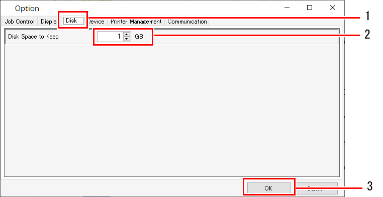
- Set a suitable value for [Disk Space to Keep].
- Set the minimum free space on the hard disk where the work folder is located.
- Job execution is canceled if the space available drops below this setting.
- Click [OK].
- Settings that have been changed will be applied after restarting RasterLink7.
Set the colorimeter
- Install the driver for the colorimeter to be used.
- Connect the colorimeter to the ripping PC.
- Select the [Device] tab in the [Environments] - [Option] dialog.
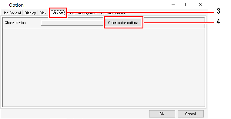
- Click [Colorimeter setting].
- The [Setup] dialog appears.
- Connect the colorimeter to the PC, then click [Check device].
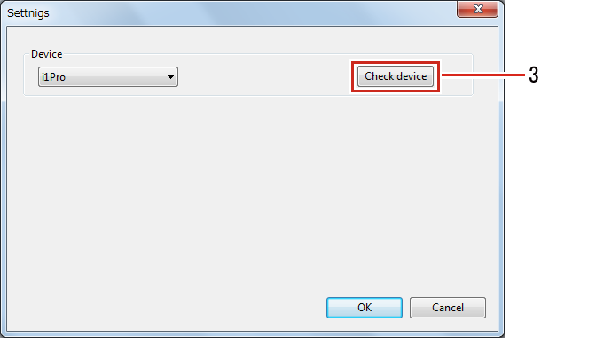
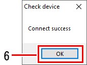
- The [Check device] dialog appears once the connection has been confirmed.
- Click [OK].
- Settings that have been changed will be applied after restarting RasterLink7.
Set the interface
When performing ID cutting, set the CuttingLink connection information.
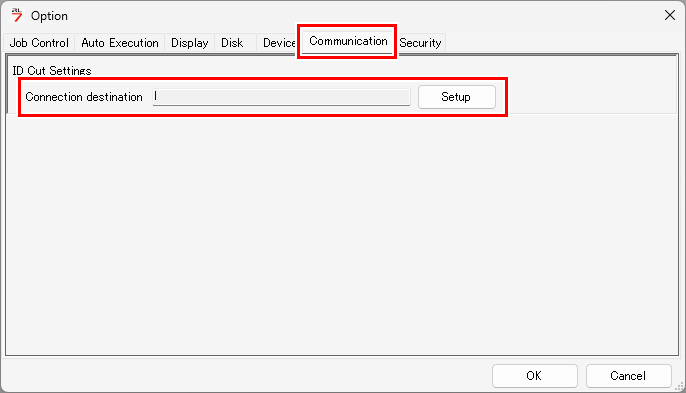
For more information, refer to the separate "ID Cut Guide".
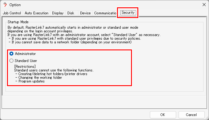
Set the security
If [Standard User] is selected while using RasterLink7 with an administrator account, RasterLink7 will launch with standard user permissions the next time.
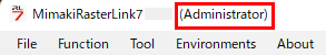
- If you are unsure of the user permissions for RasterLink7, check the area to the right of the version information in the upper-left corner of the RasterLink7 screen. The user permissions of the current user are displayed there.
If there are restrictions such as those listed below, change the permissions before use.
- If security policies require using RasterLink7 with standard user permissions
- If your environment prevents saving data to network folders
Switch to administrator permission to use them.
- Creates and deletes hot folders and printer drivers.
- Changes to the work folder
- RasterLink7 Update